This is a complete application guide for designing work access platform lifts. It includes photographs and movies illustrating optional features and views of completed units to help explain the full scope of available customization. We aim to stir your imagination so that, working together, we can optimize a design to fit your application perfectly.
Our White Paper ”Work Access Lift Application Guide” is a condensed 2 page PDF version of this site that can be printed as a handout and used as an offline work reference. Please scroll through this entire page before printing the White Paper so that you can benefit from the many extra details that we offer in this complete design guide.
WHY USE WORK ACCESS LIFTS
Safety is the prime purpose of all work access platform lifts. These work access platforms are designed to move production personnel, tools, and materials to sound positions to enhance worker safety and ergonomic efficiency. The alternatives to these lifts include ladders, scaffolding, or simply allowing workers to work in awkward, tiring, or dangerous positions.
WHERE TO USE WORK ACCESS LIFTS
Production applications are broadly varied and may include welding, painting, assembly, fabrication, inspection, and maintenance. Because each application is unique to the task performed and the object worked on, each lift must be custom-designed to the specific application. This guide is designed to help you organize and prioritize your requirements so they may be resolved into appropriate specifications for your hydraulic access platform lift.
PLATFORM SIZE AND CONFIGURATION:
1. Overall size:
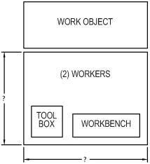
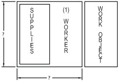
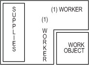
The first consideration is the overall room required for personnel, tools, materials and work aids such as tables, work benches, jib cranes, tool cribs or boxes, and any other items that will enhance worker efficiency. Be sure that the surface area is large enough so that personnel are not crowded or cramped. Adequate maneuvering room is only assured when everything on the platform is accounted for including the maximum number of personnel. A good starting point is to draw a scaled plan view of the work object outline and the adjacent access lift platform outline with top views of all the objects you intend to place on the lift. This is your best insurance so that there will be adequate room for everything on the platform.
2. Cutouts and/or platform extensions:
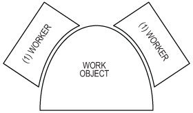
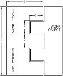
The scaled drawing of the work object and the lift platform can also be used to determine if any platform extensions or cutouts are required. When a straight-sided platform does not interface well with the item worked on, the footprint of the lifting mechanism beneath the work surface often dictates whether providing platform extensions or platform cutouts makes more sense. Sometimes, both are needed. Extensions may be permanent, fold down (hinged), or powered horizontal extensions. Obviously, the more complicated things are, the more expensive they are. Be sure that we are provided an accurate, dimensioned sketch of the required plat for the outline. With over 1500 standard products, small increments can determine whether a standard lifting mechanism can be used or a more expensive custom engineered lift will be required. We will let you know if there is a near miss to a standard product that can save you money.
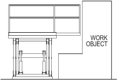
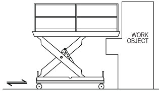
3. Shear point elimination:
When a platform is being elevated to a work height, it is important that personnel on the platform are protected from any shear points that may be created between the edge of the moving platform and the adjacent work object. The easiest way to check this is to draw a side view profile of the interface between the work object and the vertical movement of the platform edge. Projections on the work object are the danger points that may require accommodation. There are many options. One is to position the lift to create a minimum of a 4” gap between the platform and the work object. Controls can be positioned on the platform so that the operator must stand back from the working edge in order to elevate the platform. Hinged platform extensions can be used to create a large gap during platform elevation and then lowered to the horizontal position when actual work is being done. Vertical rising guardrails, swing gates, or removable handrails can be used during elevating operations. These barriers can then be removed when the lift is positioned, and the actual work begins. Mobile units may be elevated away from the object and then propelled next to the object after the desired work height. Sometimes, simple signage to stand back and hold onto guardrails while elevating operations may suffice. Industrial engineers can be very creative as long as they remember to address this issue and protect the riders during the lift movement.
4. Platform surfaces:
These may be embossed safety treads, the most common, smooth steel with silica sand for slip resistance, open grating, rubber mats, or wood surfaces. The metal surfaces can be carbon steel, stainless steel, or aluminum and may be finished with industrial enamel, epoxy paint, zinc finishes such as Galvacon or stainless steel finished with products like Steel-it. Hot dipped galvanizing is not recommended as it may cause warping. Platform extensions may be made of material different from the basic platform.
5. Safety options:
There are many safety options to consider. Guardrails can be designed in any configuration and they can be equipped with many styles of gates or chains to suit the applications. They can be vertical folding, swinging, removable, and retracting into the platform. Electrical interlocks can prevent vertical movement unless guardrails or gates are in place and electrical eyes can be used. Bellows can be used to cover scissor leg assemblies. Personnel harnesses can be used. Common sense is the primary guide.
6. Other options:
Work aids such as those mentioned in paragraph 1 above can be added by either the customer or the lift manufacturer. The manufacturer must approve jib cranes that cantilever loads over the platform’s edge to ensure tipping moments are acceptable. Portability options must be added by the lift manufacturer and discussed on the next page.
CAPACITY
Once you have completed your shopping list of work aids to place on the platform, you can begin to add up the total weight on board. Add the weight of the tools, materials, and work aids. Add the weight of the live load (personnel), and do not forget that every once in a while, extra supervisors may wish to come along. Most manufacturers size their lifts in 2000lb. increments so you can round up to the next multiple of 2000 lbs. Do not worry about adding any safety factors as reputable lift builders build to ANSI code MH29.1 which requires 3 to 1 safety factors.
TRAVEL
Determine the lift height that you must reach. Subtracting the lowered height of the stored platform lift will yield the required travel. Note that most single scissor lifts can only provide vertical travel 75% of the platform length or less. If the platform length is too short for the desired travel, then we will have to go to a multiple scissor lift. This is fine, except the cost of multiple scissors is greater than that of single scissor lifts, so if you are close, getting a platform that is longer than you need may be less expensive. Also, multiple scissor lifts have a higher lowered height than single scissor lifts; therefore, a step may have to be added to the end or side of the lift. If you are going to add a portability feature, be aware that this may add 2” to 10” to the lowered height depending upon the specific features required.
POWER UNITS
Typical power requirements are 230/460 v. 60 Hz. 3 ph. Other voltages are available on request. The power unit locations are most commonly beneath the platforms. Still, larger units may require locating the bulkier power units adjacent to the lifts or in some cases, mounted on the platforms.
CONTROLS
The only kind of controls allowed in ANSI MH29.1 for rider scissor lifts are constant pressure pushbuttons on the platforms. They may be permanently mounted in fixed locations or on coil cords. Automated “send” and “call” buttons are not allowed. Manual lowering valves on the base of the unit may be added for lowering if there is a power outage, and limit switches for the top of travel may also be added.
PORTABILITY FEATURES
ANSI MH29.1 does not allow for drive around portable lifts such as self propelled work platforms covered by ANSI 92.6. The MH29.1 units are limited to self propelled units that are guided in some way such as on tracks. Units with fork pockets or lifting eyes for pick and place portability are common. Manually propelled scissor lifts are covered by ANSI 92.3, and these units with casters may require outriggers and floor locks, but they are well within our capabilities.
CUSTOM SOLUTIONS FOR UNIQUE APPLICATIONS
The uniqueness of each work access lift application rules out any standard lift model, but with a little forethought and problem analysis, excellent solutions are fairly easy to achieve. The advantages of lifts over ladders and scaffolding are obvious and the benefits of worker comfort, efficiency, and safety mean the payback period on these investments is usually very short. We at Advance Lifts have built many configurations of work access platform lifts and are eager to help you design a perfect fit for your application.
Work Access lift options
TYPICAL PLAN VIEWS
CURVED PLATFORMS
INTENTED PLATFORMS
PLATFORMS EXTENSIONS
GUIDED ROLLING PLATFORMS
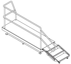
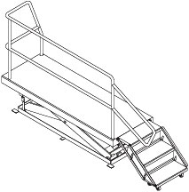
ARTICULATED STAIRS
Call the number below with any questions you have about our personnel lift platforms.