
A White Paper
This section deals with tilters, upenders, bin-tilters and dumpers. All of these devices are similar in that they all rotate angularly about a horizontal axis. The differences are the degree of rotation, the type of loads and the configuration of the platforms or bins. The basic information necessary to select an appropriate tilter for an application includes all of the topics listed below:
- Capacity
- Nature of the load
- Means of loading and unloading
- Lowered height and tilt
- Platform and bin size
- Speed requirement
- Power and Duty cycle requirements
- Special features and accessories
The following discussions will be used to clarify the meanings of these topics, point out special considerations to be aware of, and provide us with a common vocabulary.
Capacity: The capacity of a unit is the total weight being placed on a unit and consists of the total live load + the total dead load as described below:
Live Load Weight And Description: Live loads are the items that will be placed on the unit and removed from the unit. It is important to know the maximum weight. It should also be noted if the load will be unbalanced due to a lopsided or irregular configuration or a loading operation that can cause temporary uneven loads.
Dead Load Weight And Description: Tilters and upenders may have a dead load weight that is applied to the unit on a permanent basis such as conveyor, weight scales, or fixtures. A good description including how the dead weight will be supported by the platform and attached to the platform is necessary so that our engineers can determine if the structure of our standard platform can satisfactorily support the incurred loads without deflection or twisting. Any unbalanced loads such as offset conveyor drive motors must be mentioned so that the center of balance for fully loaded and minimally loaded configurations can be determined.Any extensions to platforms must also be noted as they may effect the tilting capacity of the unit.
 Nature of the load: This requires a good description of what the load consists of, the weights of the load components, the location of the center of gravity of the load and the physical dimensions of the load. Our concern here is with very long loads (such as tall cabinets or refrigerators) or unusually configured loads (such as transformers or fork truck counter weights) that can place the center of gravity of the load outside of our design parameters. These items can be handled very easily if we know the location of the center of gravity, but they do not conform to our standard catalog ratings.
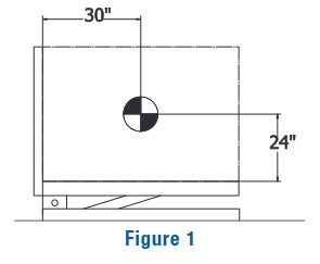
The capacity rating of a tilting unit in our catalog is based on the center of gravity of the load being no farther away from the tilting axis than the center of the tilting platform. As an example, Figure 1 depicts an upender with a 48″ x 48″ platform and a 48″ x 60″ platform and a capacity rating of 6000 lbs.For design purposes, our engineer will assume that the center of gravity of the 6000 lb. load will be no more than 24″ away from the 60″ long platform and no more than 30″ away from the 48″ long platform.
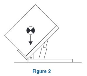 These loading assumptions are consistent with all tilting products. Basic tilters that have only one platform and a perpendicular retainer lip, are designed with a lip height appropriate for the load center of gravity being no more than 24″ above the tilting platform. Figure 2, illustrates a 45-degree tilter with a 36″ long platform.
The side to side loading on the platform should be approximately centered and a maximum capacity load should be positioned with the center of gravity within 6″ of the center of the width. In the case of reduced loads, all tilters are designed to handle half the load on half of the platform.
If you encounter loads that do not fit within our design parameters, please contact us.We can either design a custom unit or determine which standard tilter will meet your needs with or without modification.
Means Of Loading And Unloading: Loading of a tilter is usually a simple process of placing loads onto the units in the fully lowered position, which will put no undo stress on the units. There is a complete discussion of loading issues in the lift application section of this catalog beginning on page 11. Most of those concerns do not apply to tilters. The one concern that applies to everything we manufacture is high impact loading from dropped loads or high speed loading impact. If you encounter a high impact loading application, give us the details of the operation and we will tell you what needs to be done to protect our equipment.
Lowered Height And Tilt: The lowered height of a unit in the catalog can not be reduced. Building up the base frame can increasethe lowered height of a unit. If an application absolutely requires a lower lowered height, then you should consult with the factory for a quote on a special design unit.
The degree of tilt for a unit can always be reduced electrically and/ or mechanically. Increasing the degree of tilt usually requires modification or a special design; therefore you must consult with the factory for pricing.
Platform And Bin Size: The platform sizes must fall within the maximum and minimum sizes shown in the catalog. Note that if something is affixed to our platform like a conveyor or other device, it must also fall within the maximum size constraints listed for our platform as the attached device in fact becomes the platform. Bin sizes may be altered, but the factory must be consulted for the cost increases.
Speed Requirements: Speed is usually not an issue in tilter applications. However, if our catalog tilting times are not satisfactory for an application please contact the factory with your requirement and we will quote on a modification to meet the need.
Power And Duty Cycle Requirements: The actual power available at the intended location of the equipment should be confirmedat the beginning of the selection process. Note that some units will not operate at catalog speeds on single-phase currents. On airapplications, PSI and CFM availability at the equipment site must also be confirmed.
When considering the duty requirements of the tilter, it is necessary to think in terms of two (2) systems, the tilting mechanism and the power unit. It is necessary to know whether the tilter application requires full stroke movement or will there be a series of incremental “jogs” in one of the directions. Specifically, we need the time intervals between operations and the direction and size of movement in each operational increment. Finally, the total number of cycles per hour, day and year should be calculated.