
Why Use Rail Transfer Bridges
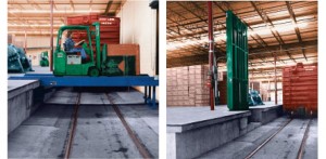 The primary use of rail transfer bridges is to span from floor to floor or dock to dock over railroad tracks. The platforms are left in the horizontal position most of the time and then elevated to the vertical position when trains need to pass on the railroad spur. In the most common application there is a single loading dock bridge recessed in the face of one floor or dock and when the bridge is lowered, the traveling end of the platform rests in a recess on the opposing dock. Sometimes due to overhead clearance problems or very long spans, two railroad loading dock bridges are positioned end to end, each hinged on opposing docks so that their traveling ends meet in the middle of the span. In these instances, the traveling ends of the rail transfer bridges are either supported by a concrete pier or each bridge leaf is equipped with automatic folding legs.
Note that if a unit is specified that is wide enough for two way traffic, then the lift bridge capacity specified must exceed the combined weight of the passing traffic and the axle capacity rating must exceed the combined maximum axle weight of the two (2) passing vehicles. Sometimes it is more economical to install two (2) narrower units; each limited to one way traffic.
Call us at 1-800-843-3625 with any questions you have about our railroad loading dock bridges.
ARCHITECTURAL SPECIFICATIONS FOR RAIL TRANSFER BRIDGES
SCOPE: This specification covers Advance Lifts, Inc. Rail Transfer Bridge model number “ A ”.
Platform: The bridge deck shall be “ B ” wide x “ D ” minus 2-1/2″ long. The clear span between docks is “ C ”. (Actual platform length is clear span plus 24″ for the ram cutout, plus 6″ for lip cutout, less 1″ clearance at the lip end and 1-1/2″ at the ram end.) The bridge shall have a safety tread steel deck and be fabricated from structural steel shapes and forms, which are rigidly welded and reinforced for maximum stability and minimum deflection.
Capacity: The lift bridge shall have a loading capacity of “ E ” with an axle capacity of “ F ” at a traffic speed of 3 mph.
Travel: The bridge travel shall be a full 90º arc so that none of the bridge mechanism projects beyond the dock when fully raised.
Rams: The bridge shall be equipped with “ G ” heavy duty double acting hydraulic rams which have chrome plated rods to inhibit rusting. The rams shall also be equipped with steel internal cylinder stops and ceramic wear rings for long life and velocity fuses.
Eletrical Control: The bridge shall be equipped with two (2) NEMA 1 “deadman” style wall mounted pushbutton control stations (one for each dock) and a UL approved controller assembly consisting of a NEMA 12 control box, magnetic motor starter and a 24 V. control transformer with fused secondary and primary.
Power Unit: The electrical power unit shall be self-contained with all components built onto a single oil reservoir. It shall consist of a continuous duty 5HP 230/460V-60HZ-3PH motor, high pressure pump, counter balance valve, oil filters and mild steel reservoir. The overall dimensions shall be approximately 22″ x 20″ x 21″ H.
Speed: The bridge shall raise in “ I ” seconds.
Work to be performed by owner: All electrical work, excavation, concrete work, building modifications, pit angle framing, underground piping and embedded items.
Work to be performed by Installer: Furnish the hydraulic oil and install the bridge complete less the above exceptions.
Specification Table for Rail Transfer Bridges
| A | Model No. | 14-101 | 14-102 | 14-103 | 14-104 | 14-105 | 14-106 | 14-107 | 14-108 | 14-109 | 14-110 | 14-111 | 14-112 | 14-113 |
|---|---|---|---|---|---|---|---|---|---|---|---|---|---|---|
| B | Width | 6′ | 6′ | 6′ | 6′ | 6′ | 6′ | 6′ | 6′ | 6′ | 6′ | 6′ | 6′ | 6′ |
| C | Clear Span at Docks | 14′ | 15′ | 16′ | 17′ | 18′ | 14′ | 15′ | 16′ | 17′ | 18′ | 14′ | 15′ | 16′ |
| D | Overall span* | 16-1/2′ | 17-1/2′ | 18-1/2′ | 19-1/2′ | 20-1/2′ | 16-1/2′ | 17-1/2′ | 18-1/2′ | 19-1/2′ | 20-1/2′ | 16-1/2′ | 17-1/2′ | 18-1/2′ |
| E | Capacity | 10000 | 10000 | 10000 | 10000 | 10000 | 15000 | 15000 | 15000 | 15000 | 15000 | 20000 | 20000 | 20000 |
| F | Axle Capacity | 8000 | 8000 | 8000 | 8000 | 8000 | 12000 | 12000 | 12000 | 12000 | 12000 | 16000 | 16000 | 16000 |
| G | Rams | 1 | 1 | 2 | 2 | 2 | 1 | 1 | 2 | 2 | 2 | 2 | 2 | 2 |
| H | Weight | 3800 | 4000 | 4500 | 4700 | 4900 | 4200 | 4400 | 4400 | 5000 | 5200 | 4800 | 5200 | 5500 |
| A | Model No. | 14-114 | 14-115 | 14-116 | 14-117 | 14-118 | 14-119 | 14-120 | 14-121 | 14-122 | 14-123 | 14-124 | 14-125 | |
|---|---|---|---|---|---|---|---|---|---|---|---|---|---|---|
| B | Width | 6′ | 6′ | 6′ | 6′ | 6′ | 6′ | 6′ | 6′ | 6′ | 6′ | 6′ | 6′ | |
| C | Clear Span at Docks | 17′ | 18′ | 14′ | 15′ | 16′ | 17′ | 18′ | 14′ | 15′ | 16′ | 17′ | 18′ | |
| D | Overall span* | 19-1/2′ | 20-1/2′ | 16-1/2′ | 17-1/2′ | 18-1/2′ | 19-1/2′ | 20-1/2′ | 16-1/2′ | 17-1/2′ | 18-1/2′ | 19-1/2′ | 20-1/2′ | |
| E | Capacity | 20000 | 20000 | 25000 | 25000 | 25000 | 25000 | 25000 | 30000 | 30000 | 30000 | 30000 | 30000 | |
| F | Axle Capacity | 16000 | 16000 | 20000 | 20000 | 20000 | 20000 | 20000 | 24000 | 24000 | 24000 | 24000 | 24000 | |
| G | Rams | 2 | 2 | 2 | 2 | 2 | 2 | 2 | 2 | 2 | 2 | 2 | 2 | |
| H | Weight | 5700 | 5900 | 5000 | 5300 | 5500 | 5800 | 6100 | 5200 | 5500 | 5800 | 6100 | 6400 |
| A | Model No. | 14-201 | 14-202 | 14-203 | 14-204 | 14-205 | 14-206 | 14-207 | 14-208 | 14-209 | 14-210 | 14-211 | 14-212 | 14-213 |
|---|---|---|---|---|---|---|---|---|---|---|---|---|---|---|
| B | Width | 7′ | 7′ | 7′ | 7′ | 7′ | 7′ | 7′ | 7′ | 7′ | 7′ | 7′ | 7′ | 7′ |
| C | Clear Span at Docks | 14′ | 15′ | 16′ | 17′ | 18′ | 14′ | 15′ | 16′ | 17′ | 18′ | 14′ | 15′ | 16′ |
| D | Overall span* | 16-1/2′ | 17-1/2′ | 18-1/2′ | 19-1/2′ | 20-1/2′ | 16-1/2′ | 17-1/2′ | 18-1/2′ | 19-1/2′ | 20-1/2′ | 16-1/2′ | 17-1/2′ | 18-1/2′ |
| E | Capacity | 10000 | 10000 | 10000 | 10000 | 10000 | 15000 | 15000 | 15000 | 15000 | 15000 | 20000 | 20000 | 20000 |
| F | Axle Capacity | 8000 | 8000 | 8000 | 8000 | 8000 | 12000 | 12000 | 12000 | 12000 | 12000 | 16000 | 16000 | 16000 |
| G | Rams | 2 | 2 | 2 | 3 | 3 | 2 | 2 | 2 | 3 | 3 | 2 | 2 | 2 |
| H | Weight | 4800 | 5000 | 5300 | 5700 | 6000 | 5200 | 5400 | 5700 | 6200 | 6500 | 5900 | 6100 | 6500 |
| A | Model No. | 14-214 | 14-215 | 14-216 | 14-217 | 14-218 | 14-219 | 14-220 | 14-221 | 14-222 | 14-223 | 14-224 | 14-225 | |
|---|---|---|---|---|---|---|---|---|---|---|---|---|---|---|
| B | Width | 7′ | 7′ | 7′ | 7′ | 7′ | 7′ | 7′ | 7′ | 7′ | 7′ | 7′ | 7′ | |
| C | Clear Span at Docks | 17′ | 18′ | 14′ | 15′ | 16′ | 17′ | 18′ | 14′ | 15′ | 16′ | 17′ | 18′ | |
| D | Overall span* | 19-1/2′ | 20-1/2′ | 16-1/2′ | 17-1/2′ | 18-1/2′ | 19-1/2′ | 20-1/2′ | 16-1/2′ | 17-1/2′ | 18-1/2′ | 19-1/2′ | 20-1/2′ | |
| E | Capacity | 2000 | 20000 | 25000 | 25000 | 25000 | 25000 | 25000 | 30000 | 30000 | 30000 | 30000 | 30000 | |
| F | Axle Capacity | 16000 | 16000 | 20000 | 20000 | 20000 | 20000 | 20000 | 24000 | 24000 | 24000 | 24000 | 24000 | |
| G | Rams | 3 | 3 | 2 | 2 | 2 | 3 | 3 | 2 | 2 | 2 | 3 | 3 | |
| H | Weight | 7000 | 7300 | 6200 | 6400 | 6800 | 7300 | 7600 | 6500 | 6700 | 7100 | 7600 | 7900 |
| A | Model No. | 14-301 | 14-302 | 14-303 | 14-304 | 14-305 | 14-306 | 14-307 | 14-308 | 14-309 | 14-310 | 14-311 | 14-312 | 14-313 |
|---|---|---|---|---|---|---|---|---|---|---|---|---|---|---|
| B | Width | 8′ | 8′ | 8′ | 8′ | 8′ | 8′ | 8′ | 8′ | 8′ | 8′ | 8′ | 8′ | 8′ |
| C | Clear Span at Docks | 14′ | 15′ | 16′ | 17′ | 18′ | 14′ | 15′ | 16′ | 17′ | 18′ | 14′ | 15′ | 16′ |
| D | Overall span* | 16-1/2′ | 17-1/2′ | 18-1/2′ | 19-1/2′ | 20-1/2′ | 16-1/2′ | 17-1/2′ | 18-1/2′ | 19-1/2′ | 20-1/2′ | 16-1/2′ | 17-1/2′ | 18-1/2′ |
| E | Capacity | 10000 | 10000 | 10000 | 10000 | 10000 | 15000 | 15000 | 15000 | 15000 | 15000 | 20000 | 20000 | 20000 |
| F | Axle Capacity | 8000 | 8000 | 8000 | 8000 | 8000 | 12000 | 12000 | 12000 | 12000 | 12000 | 16000 | 16000 | 16000 |
| G | Rams | 2 | 2 | 2 | 3 | 3 | 2 | 2 | 2 | 3 | 3 | 2 | 2 | 2 |
| H | Weight | 5100 | 5400 | 5700 | 6100 | 6400 | 5500 | 5800 | 6100 | 6600 | 6900 | 600 | 6500 | 6900 |
| A | Model No. | 14-314 | 14-315 | 14-316 | 14-317 | 14-318 | 14-319 | 14-320 | 14-321 | 14-322 | 14-323 | 14-324 | 14-325 | |
|---|---|---|---|---|---|---|---|---|---|---|---|---|---|---|
| B | Width | 8′ | 8′ | 8′ | 8′ | 8′ | 8′ | 8′ | 8′ | 8′ | 8′ | 8′ | 8′ | |
| C | Clear Span at Docks | 17′ | 18′ | 14′ | 15′ | 16′ | 17′ | 18′ | 14′ | 15′ | 16′ | 17′ | 18′ | |
| D | Overall span* | 19-1/2′ | 20-1/2′ | 16-1/2′ | 17-1/2′ | 18-1/2′ | 19-1/2′ | 20-1/2′ | 16-1/2′ | 17-1/2′ | 18-1/2′ | 19-1/2′ | 20-1/2′ | |
| E | Capacity | 20000 | 20000 | 25000 | 25000 | 25000 | 25000 | 25000 | 30000 | 30000 | 30000 | 30000 | 30000 | |
| F | Axle Capacity | 16000 | 16000 | 20000 | 20000 | 20000 | 20000 | 20000 | 24000 | 24000 | 24000 | 24000 | 24000 | |
| G | Rams | 3 | 3 | 2 | 2 | 2 | 3 | 3 | 2 | 2 | 2 | 3 | 3 | |
| H | Weight | 7400 | 7700 | 6500 | 6800 | 7200 | 7700 | 8000 | 6800 | 7100 | 7500 | 8000 | 8300 |
NOTE:
“I” Speed – 1 ram=60 sec., 2 rams=120 sec., 3 rams=180 sec.
* Actual platform length is “D” (overall span length) minus 2-1/2″.
Please note that we have made lift bridges up to 100,000 lb. capacity. If you do not see what you need, simply consult the factory