A White Paper
Safety is the prime purpose of all work access lifts. They are designed to move production personnel, their tools and materials to ergonomically sound work positions to enhance both worker safety and efficiency. Production tasks are broadly varied and may include welding, painting, assembly, fabrication, inspection, and maintenance. Because each application is unique to the task being performed and the object being worked on, each work platform lift must be custom designed to the specific application. This guide is designed to help you organize and prioritize your requirements so they may be resolved into appropriate specifications for your work access lift.
Platform size and configuration:
1. Overall size:
The first consideration is the space needed for personnel, tools, and work aids such as tables, workbenches, jib cranes, tool cribs or boxes, and other items that improve worker efficiency. Ensure the platform’s surface area is sufficiently large to prevent personnel from feeling crowded or cramped. An adequate maneuvering room can only be guaranteed when all items on the platform, alongside the workers, are considered.
2. Cutouts and platform extensions:
When a straight-sided platform does not align well with the item being worked on, the footprint of the lifting mechanism beneath the work surface often determines whether platform extensions or cutouts are more appropriate. In some cases, both may be necessary. Extensions can be permanent, fold-down (hinged), or powered horizontal extensions. Naturally, the more complex the design, the higher the cost. Be sure to provide the lift manufacturer with an accurate, dimensioned sketch of the required platform profile.
3. Platform surfaces:
These may be embossed safety tread, which is most common, smooth steel with silica sand for slip resistance, open grating, or wood surfaced. The materials can be carbon steel, stainless steel, or aluminum and may be finished with industrial enamel, epoxy paint, zinc finishes such as Galvacon, or stainless steel finished with products like Steel-it. Hot-dipped galvanizing is not recommended as it may cause warping. Platform extensions may be made of material different from the basic platform.
4. Shear point elimination:
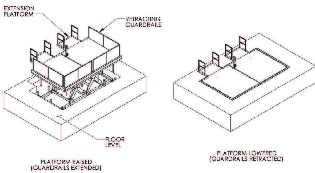
When a platform is being elevated to a working height, personnel on the platform must be protected from any shear points created between the edge of the moving platform and the adjacent work object. There are many options. One is to position the lift to make a minimum of a 4″ gap between the platform and the work object. Controls can be placed on the platform so the operator must stand back from the working edge to elevate the platform. Hinged platform extensions can be utilized to create a bigger gap during platform elevation and then be lowered to a horizontal position when work is being performed. Vertical rising guardrails, swing gates, or removable handrails can also be implemented during elevating operations. Mobile units may be raised away from the work object and then moved into position once the desired work height is reached. In some cases, simple signage instructing personnel to stand back and hold onto guardrails during elevation may be sufficient. Industrial engineers have a range of creative solutions, provided this issue is carefully addressed.
5. Safety options:
There are many safety options to consider. Guardrails can be designed in any configuration, and they can be equipped with many styles of gates or chains to suit the applications. They can be vertical folding, swinging, removable, and retracting into the platform. Electrical interlocks can prevent vertical movement unless guardrails or gates are in place. Electric eyes can be used. Bellows can be used to cover scissor leg assemblies. Personnel harnesses can be used. Common sense is the primary guide.
6. Other options:
Work aids such as those mentioned in paragraph 1 above can be added by either the customer or the lift manufacturer. Jib cranes which cantilever loads over the edge of the platform must be approved by the manufacturer to be sure tipping moments are acceptable. Portability/mobility options must be added by the lift manufacturer and are discussed below.
Capacity:
After finalizing your list of work aids for the platform, calculate the total weight to be supported. Include the weight of tools, materials, and work aids, as well as the live load (personnel). Remember to account for occasional additional personnel, such as supervisors. Most manufacturers size their lifts in 2,000 lb. increments, so round up to the next multiple of 2,000 lbs. There’s no need to add extra safety factors, as reputable lift manufacturers adhere to ANSI code MH29.1, which requires a 3-to-1 safety factor.
Travel:
Determine the lift height needed to reach your desired work level. Subtract the lowered height of the stored platform lift to calculate the required travel distance. Keep in mind that most single scissor lifts can provide vertical travel up to 75% of the platform length or less. If the platform length is insufficient for the required travel, a multiple scissor lift may be necessary. While multiple scissor lifts are effective, they are typically more expensive than single ones. In some cases, opting for a slightly longer platform may be a more cost-effective solution. Additionally, multiple scissor lifts usually have a higher lowered height than single scissor lifts, which may necessitate adding a step at the end or side of the lift. If portability features are included, be aware that these may increase the lowered height by 2″ to 10″, depending on the specific features required.
Power units:
Typical power requirements are 230/460 V, 60 Hz, 3-phase. Other voltage options are available upon request. Power units are most commonly located beneath the platforms, but larger units may need to be positioned adjacent to the lifts or, in some cases, mounted directly on the platforms.
Controls:
According to ANSI MH29.1, the only controls permitted for rider scissor lifts are constant-pressure pushbuttons located on the platform. These can be permanently mounted in fixed positions or attached to coil cords. Automated “call-send” buttons are not allowed. Manual lowering valves may be installed on the base of the unit for use during power outages, and limit switches can be added to regulate the top of travel.
Portability/mobility features:
ANSI MH29.1 does not permit drive-around portable lifts, such as self-propelled work platforms covered under ANSI 92.6. Instead, MH29.1 units are limited to self-propelled lifts that must be guided in some manner, such as along tracks. Common options include units equipped with fork pockets or lifting eyes for pick-and-place portability. Manually propelled scissor lifts with casters and floor locks are also compliant and fall well within our capabilities.
Custom Application
The uniqueness of each work access lift application rules out any standard lift model, but excellent solutions are relatively easy to achieve with a bit of forethought and problem analysis. The advantages of power lift platforms over ladders and scaffolding are obvious. The benefits of worker comfort, efficiency and safety means the payback period on these investments is usually very short. We at Advance Lifts have built many configurations of work access lifts and are eager to help you design a perfect fit for your application.
Henry J. Renken
President
Advance Lifts, Inc