CONCRETE PAD DIAGRAM FOR TOP OF GROUND MOUNTED LIFT MODELS
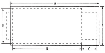
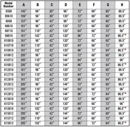
A Concrete Pad Length
B Concrete Pad Width
C Ramp Length
D Lift Length
E Lift Width
B Concrete Pad Width
C Ramp Length
D Lift Length
E Lift Width
CONCRETE PAD INSTALLATION BILL OF MATERIALS
1 One (1) Advance Model Number _________.
2 One (1) electric disconnect switch for 5 or 7-1/2HP motor.
3 One (1) plug receptacle.
4 Concrete anchor bolts and material for shimming and/or grouting.
*Seller furnishes items 1 only unless otherwise agreed to in writing.
NOTES
A Reinforce concrete to suit local soil conditions.
B All concrete work is the responsibility of the owner or his agent.
C Concrete pad must be flat and level.
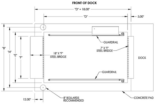
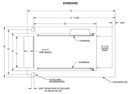
STANDARD INSTALLATION
FRONT OF DOCK INSTALLATION