
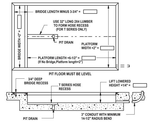
WHERE BRIDGE WIDTH IS THE SAME AS PLATFORM WIDTH
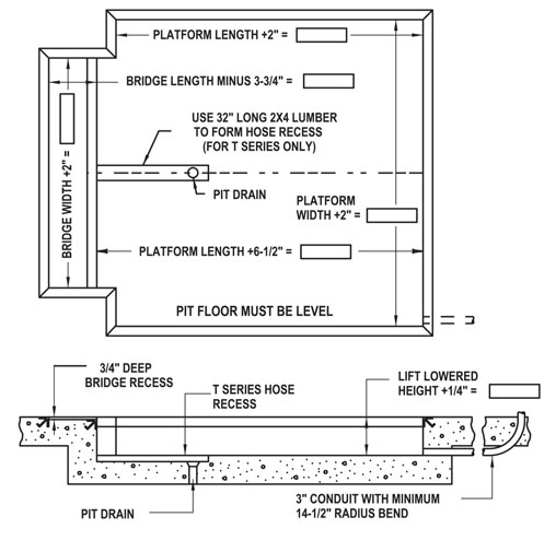
WHERE BRIDGE WIDTH IS SMALLER THAN THE PLATFORM WIDTH
NOTES
A Consult factory for pit diagram for optional wheel chock.
B Reinforce concrete to suit local soil conditions.
C All pit work and materials shown are the responsibility of owner or his agent (by pit contractor).
D Installer to run 1/2″ diameter hose(s) and plastic tubing through 3″ conduit from power unit to lift base.
E Dimension tolerances are plus 1/4″ minus 0″ (+1/4″-0″).
F 180º steel hinge bridges require a bridge recess length equal to bridge length minus 2-3/4″.
G 180º aluminum hinge bridges require a bridge recess length equal to bridge length minus 3-3/4″ and a pit length equal to platform length plus 7-1/2″.
H Consult factory for bridges longer than 30″. (18″ on 4000 Series).
INSTALLATION BILL OF MATERIALS
1 3″ x 3″ x 1/4″ curb angle as required.
2 One (1) 3″ conduit from power unit location to pit.
3 One (1) Advance Model __________.
4 One (1) electric disconnect switch for 5HP or 7-1/2HP motor.
5 ( ______) gallons of ISO46 hydraulic fluid.
6 One (1) 1/2″ SAE 100R2 hydraulic pressure hose from power unit location to lift base – 1/2″ female #8JIC threads both ends +1/4″ O.D. plastic tubing (two hoses required for 4000 Series Safetydok).
7 Concrete anchor bolts and material for shimming and/or grouting.
*seller furnishes Advance dock lift only unless otherwise agreed to in writing.
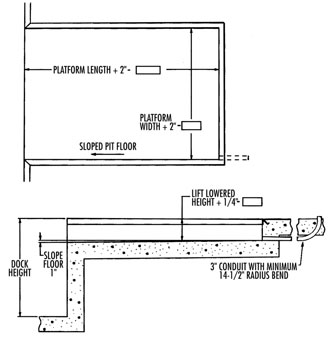
TOP OF DOCK RECESSED INSTALLATION 3 SIDED PIT
TOP OF DOCK INSTALLATION BILL OF MATERIALS
1 3″ x 3″ x 1/4″ curb angle as required.
2 One (1) 3″ conduit from power unit location to pit.
3 One (1) Advance Model _______.
4 One (1) electric disconnect switch for 5HP or 7-1/2 HP motor.
5 (________) gallons of ISO46 hydraulic fluid.
6 One (1) 1/2″ SAE 100R2 hydraulic pressure hose from power unit location to lift base 1/2″ female #8JIC threads both ends (two hoses required for 4000 Series).
7 Concrete anchor bolts and material for shimming and/or grouting.
*seller furnishes lift only unless otherwise agreed to in wri
TYPICAL RECESSED DOCK LIFT INSTALLATION AT A RAISED DOCK

TYPICAL RECESSED DOCK LIFT INSTALLATION AT GROUND LEVEL
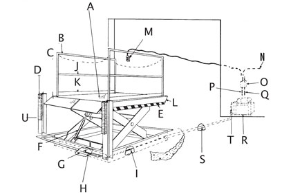
A Platform with Safety Tread Deck
B Removable Handrails with Safety Chains
C Hinged Bridge
D Rubber Dock Bumpers
E Black and Yellow Safety Striping
F Chrome Plated Rams
G Pre-Drilled Base Frame for Lagging Lift to Floor
H 48″ long Hydraulic Connecting Hose supplied by Advance Lifts, Inc. with 1/2″ Connector at center of base frame. Optional: 1/2″ x 20′ long Hydraulic Hose supplied by Advance Lifts, Inc
I Connector
J Midrail
K Kickplate
L Bevel Toe Guards 4-Sides
M Up-Down Pushbutton Station NEMA 1, 3, 3R, 4, 4X W/20′ Control Cord
N Incoming Power Source
O Motor Controller in NEMA 12 Enclosure
P To Motor on Power Unit
Q To Down Solenoid on Power Unit
R Power Unit 5 HP 230V 60Hz 3Ph motor mounted on Reservoir 26″ W x 22″ L x 21″ H (including motor) with brackets for wall mtg.
S Run 3″ Conduit from Power Unit Location to Lift Base (by others)
T Installer to run 1/2″ Hydraulic 100R2 Hose through and Plastic Return Line 3″ Conduit from Power Unit to Connecting Hose and Tub
U WF Beam or Dock face